Procedure for connecting the BlueFlasher to the PC and the Blue&Me module to the BlueFlasher system. Please follow the order indicated below to avoid possible short circuits caused by unexpected malfunctions of the Blue&Me module to be repaired.
1
Connect to the power supply and to the PC
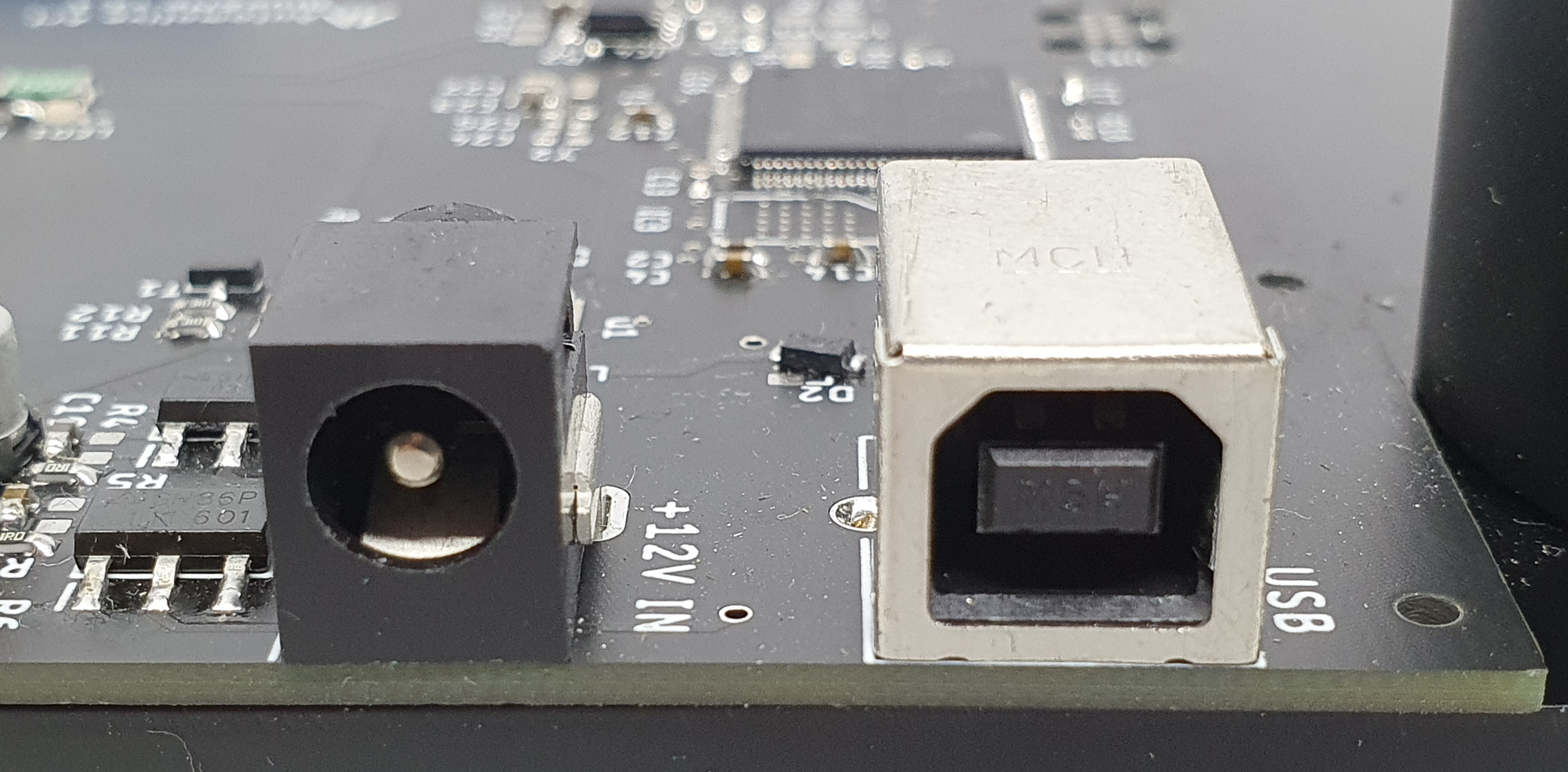
Connect the power cable from a stabilized power supply (set at 12V DC and maximum deliverable current) to the jack marked "+12V IN". Connect the USB cable to the connector marked "USB" and then to the PC.
2
Board extraction
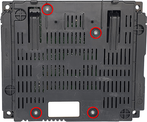
Remove the Blue&Me module from the vehicle. Unscrew the screws highlighted in the figure and extract the board.
3
J-TAG connection
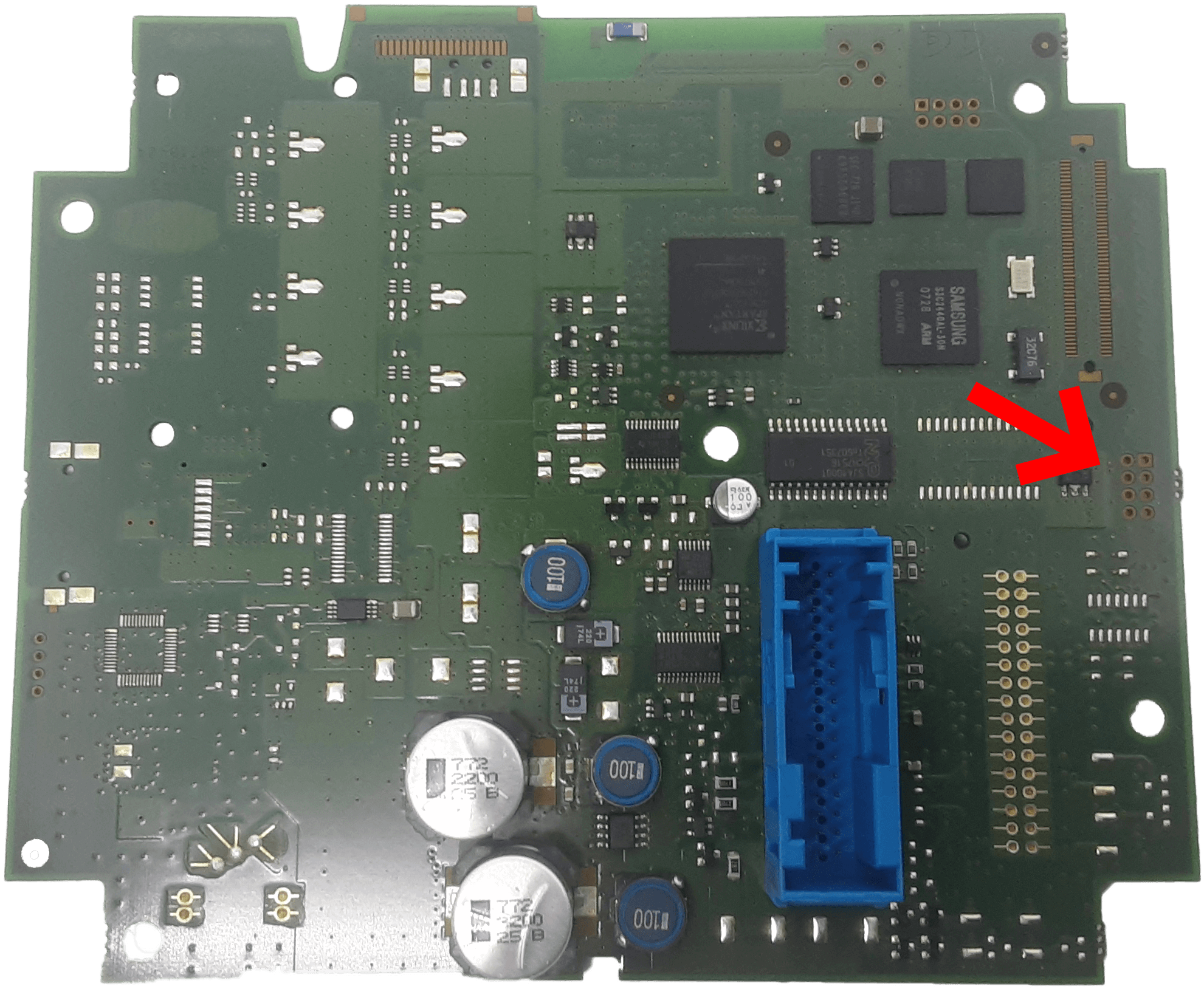
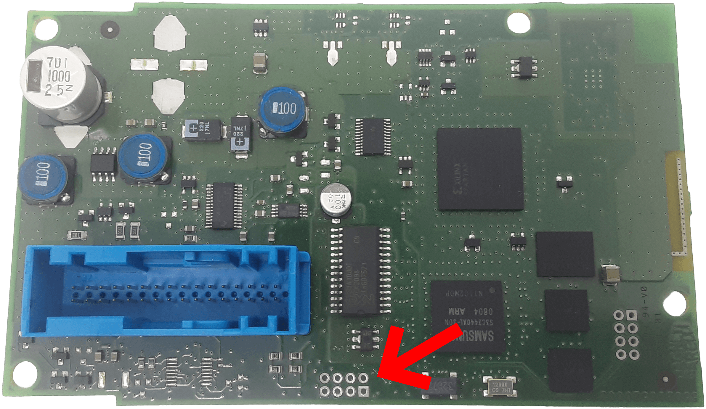
Using the clamp cable, connect the free end to the tray connector at the bottom of Blueflasher, and the other end to the Blue&Me J-TAG connector shown in the images.
4
Plug the connector
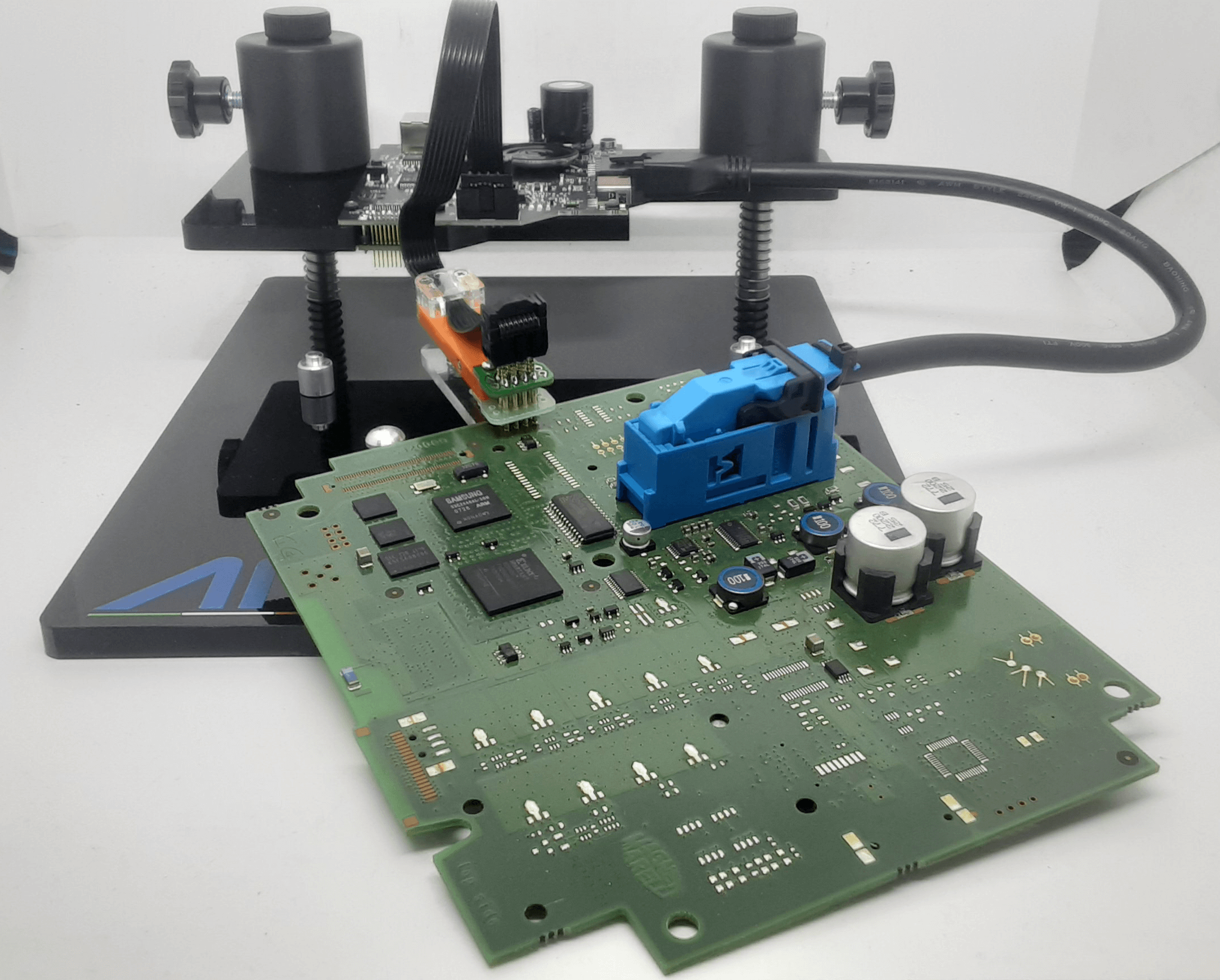
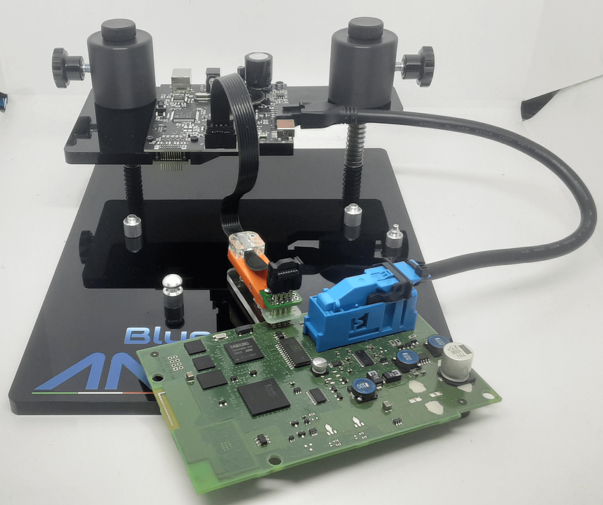
Connect the power cable to the connector on the right of Blueflasher, then attach the other end to the Blue&Me connector. The use of the template is not necessary.