Procedure for connecting the BlueFlasher to the PC and the Blue&Me module to the BlueFlasher system. Please follow the order indicated below to avoid possible short circuits caused by unexpected malfunctions of the Blue&Me module to be repaired.
1
Connect to the power supply and to the PC
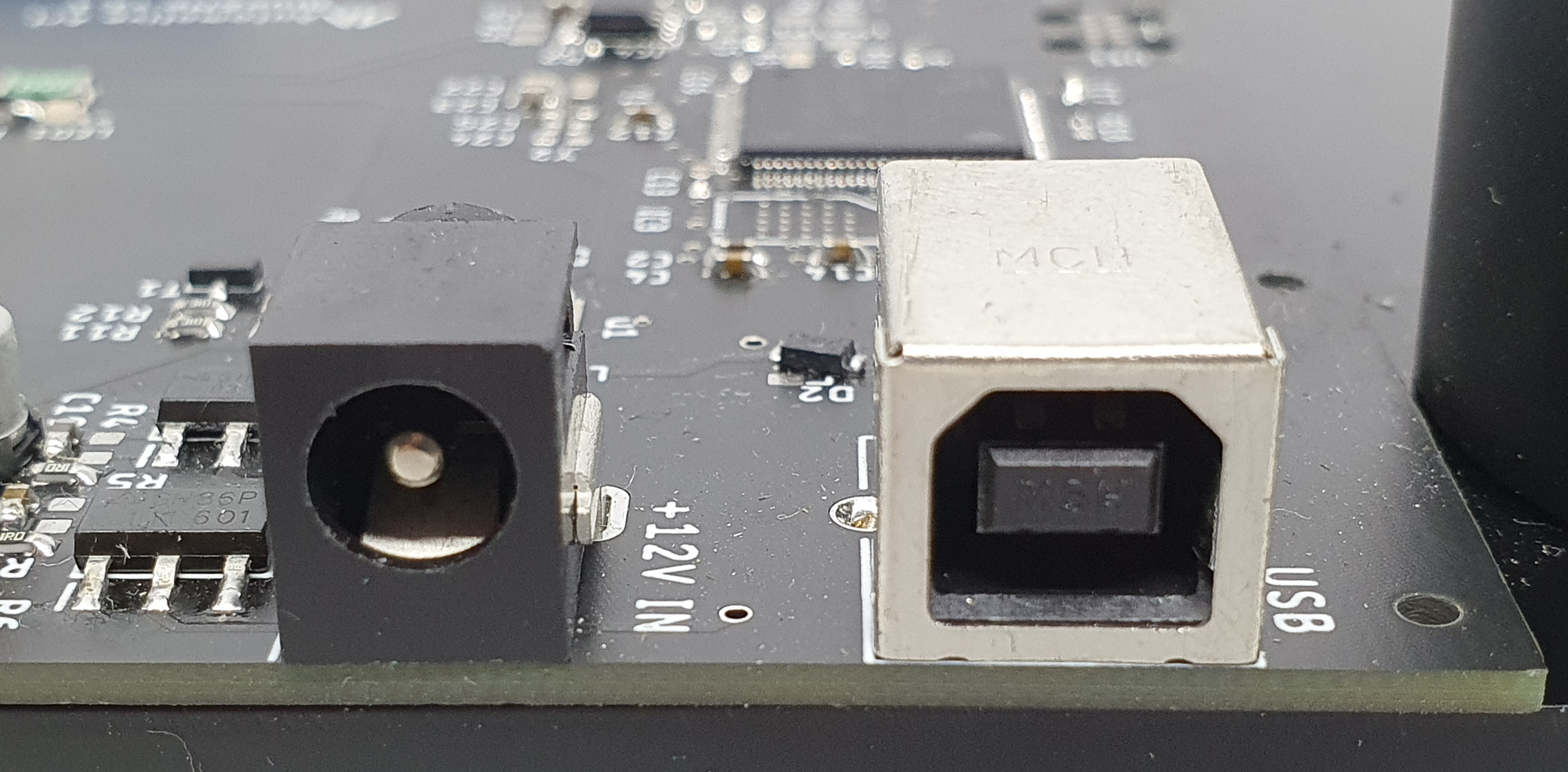
Connect the power cable from a stabilized power supply (set at 12V DC and maximum deliverable current) to the jack marked "+12V IN". Connect the USB cable to the connector marked "USB" and then to the PC.
2
Board extraction
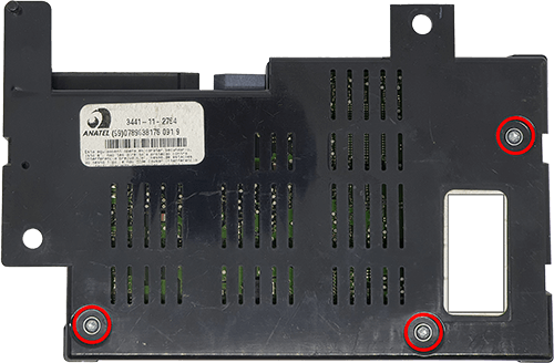
Remove the Blue&Me module from the vehicle. Unscrew the screws highlighted in the figure and extract the board.
3
Insert in template
Insert the Blue&Me board, slightly inclined, into the hollow part of the 2 lower supports (highlighted in red in the video). Lower the card until it fits into the fixed supports at the top. (highlighted in green in the video).
4
Plug the connector in the board
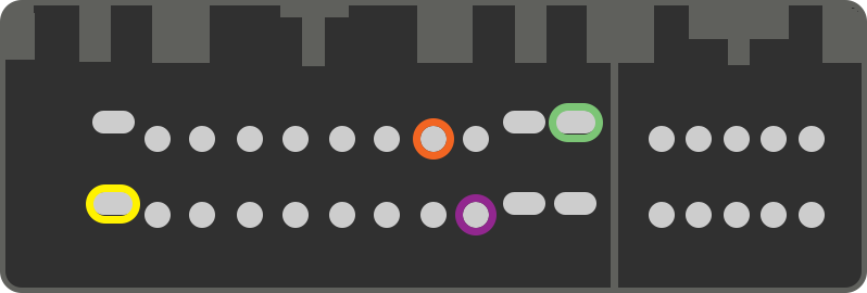
If you have the specific cable for Freemont, connect the connector to the Blue&Me card as shown in the video on the left. If you have the universal cable (For additional ADAS/ABS/UCONNECT etc. packages) connect following the diagram shown in the image on the right, keeping in mind to remove the 120 ohm resistor from the ORANGE and PURPLE cables. Finally connect the other end of the cable to BlueFlasher.